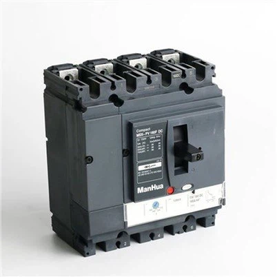
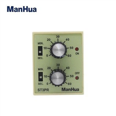
Over Voltage Under Voltage Protector
Application The over voltage under voltage protector with auto-reclosing Function is a state-of-the-art home appliance protection device designed to cater to the current commercial power situation. Its primary function is to protect against abnormal voltage, i.e., under and overvoltage. The...
Description
Application
The over voltage under voltage protector with auto-reclosing Function is a state-of-the-art home appliance protection device designed to cater to the current commercial power situation. Its primary function is to protect against abnormal voltage, i.e., under and overvoltage. The protector quickly cuts off electrical load power to safeguard the appliance and the individual if the mains voltage goes beyond the protector operating voltage.
Furthermore, when the mains voltage returns to normal, the protector automatically restores power supply with full-automatic control. The protector's two-color LED on the panel helps users to monitor its working state. The green indicator light shows that the power supply is normal, while the red light turns on when the protection function starts to cut off the power supply.
The over voltage under voltage protector boasts of several features, including but not limited to, user-friendly use, stable and reliable performance, compact structure, and elegant appearance. The device mounts on the Miniature Circuit Breaker. Overall, the product offers a seamless blend of safety and convenience, making it an indispensable appliance in modern households.
Main technical data
The power required for operation is AC230V50Hz or AC380V (three-phase four-wire). In other words, it can be powered either by a single-phase AC power supply with a voltage of 230V and frequency of 50Hz, or by a three-phase AC power supply with a voltage of 380V.
Let's talk about the maximum current that can pass through different resistive loads. The values we have to consider are 20A, 32A, 40A, 50A, 63A, 80A, and 100A. These are all maximum current values, which means that the current passing through the load should never exceed these values in order to ensure safe operation.
If we start with the lowest value, which is 20A, this represents the maximum current that can pass through a resistive load without causing any damage. Similarly, the maximum current for a resistive load of 32A is 32A and likewise for 40A, 50A, 63A, 80A, and 100A. These values are very important when it comes to selecting the right load for a particular application.
For example, if we have an electrical circuit that requires a load that can handle a maximum current of 50A, we need to choose a resistive load that can handle that value securely. Otherwise, we run the risk of overloading the load, which could cause a range of problems such as overheating or melting. Therefore, it’s critical to choose the right load for any given application and ensure that the maximum current rating is not exceeded.
The available maximum load power options are as follows: 4.4kVA, 6.6kVA, 8.8kVA, 11kVA, 13kVA, and 17kVA. These power ratings represent the maximum load that can be handled by a given device or system. It is important to choose the appropriate load power based on the requirements of the application. The higher the load power, the greater the capacity to handle larger electrical loads. It is essential to consider the specific needs and electrical demands of the equipment or system to ensure optimal performance and prevent overloading.
4. Over voltage action cutoff value; AC275V=5V
5. Over voltage recovery value: AC255V±5V
6. Under voltage action cut off value: AC175V±5V
7. Under voltage recovery value: ACI85V±5V
After a power failure, the power transmission delay should not exceed 60 seconds.
9. Action delay value: no more than 1 second
10. Installation method:35mm rail
11. Electrical life:1x10^7
Installation and dimensions
1. Dimensions(mm)see pictures
2. Altitude is less than or equal 2000m
3. Allowable temperature range -40 ℃~+50℃
4. Relative air temperature ≤85%
5. The product is Din rail 35mm.
Instructions
Please make sure that you correctly identify the input(IN) and output(OUT) for the wire over voltage under voltage protector. Additionally, ensure that the load power is lower than the product's rated power to prevent any issues. It is essential to rearrange the given information while creating a content that is highly similar to the original text. Please refrain from using ChapGPT as a reference and generate unique, original text.
The status of the product can be easily determined by observing the two LEDs on its panel. When the power is turned on, the green power indicator light turns on, while the red protection indicator light stays off, indicating normal power supply. However, if the protection is activated, the red protection indicator light turns on, serving as a warning signal. In such a case, it is necessary to start or cut off the load power as required. It is important to note that these indicators help in ensuring the smooth and safe operation of the product.
Check if the red light stops after 60 seconds of turning on the power. If it does stop, then everything is working properly. This simple test ensures that the device is functioning as intended and is ready to be used. It's important to perform this test regularly to detect any issues early on and prevent any further damage or malfunctions. Just remember to be patient and give it enough time to run its course before making any judgments.
Upon powering on, the green light will illuminate, and a countdown of 30 seconds will commence. There will be a trip if the voltage exceeds 275V or drops below 165V.
Upon powering on, the circuit initiates a reading with a flashing green light. Within 30 seconds, the circuit voltage is determined to be around 220V. At this point, the green light remains lit while the accompanying red light stays off. As the circuit voltage escalates to 275V, the red light illuminates, prompting an automatic disconnection of the load. When the voltage returns to the standard value, the green light resumes flashing. After another 30 seconds, the relay loads and activates, resulting in a consistently illuminated green light and an extinguished red light. The under voltage level remains consistent at approximately 165V.
Under certain circumstances, it is normal for only the green light to flash and initiate the countdown when debugging the overvoltage and undervoltage protector for power failure. The issue arises when the relay fails to activate the load once the countdown is complete. It is crucial to ensure that the relay successfully activates the load after the predetermined time period.
Hot Tags: over voltage under voltage protector, China over voltage under voltage protector manufacturers, suppliers, factory
Send Inquiry
You Might Also Like