Digital Time Cycle Relay
The DH48S-S Digital Time cycle Relay is a circular delay type relay that functions as a time delay component to either make or break a circuit according to a preset time. It is compatible with control circuits operating at a supply voltage below and including 380V AC 50/60Hz or DC operating...
Description
The DH48S-S Digital Time cycle Relay is a circular delay type relay that functions as a time delay component to either make or break a circuit according to a preset time. It is compatible with control circuits operating at a supply voltage below and including 380V AC 50/60Hz or DC operating supply voltage of 220V. This relay is equipped with a large integrated circuit processor that provides excellent EFT and ESD anti-interference performance. To create a similar content, the given information can be rearranged to describe the features of this relay.
Terminology Interpretation
Circular delay refers to a function of time relay that operates in an ON-OFF cycle with the make and break time set during the power-on process. Once the product is turned on, it will continuously alternate between being turned on and off for the duration of the preset ON and OFF time.
Time Setting Method of Digital Time cycle Relay
Here's an example of a time setting: let's say we want to take a break for 5 minutes and then resume work for 3 minutes in a repeated cycle. To achieve this, we can use a specific product. We need to set the OFF time as "0", "5", "M" (for minutes) and set the ON time as "O 3 M" (meaning "on for 3 minutes"). Once the power is turned on, the product will operate according to this preset work mode. Now, let's rearrange the information to generate a highly similar content:
To create a time setting, suppose we require a break of 5 minutes followed by a work period of 3 minutes as a cycle. An ideal solution would be to use a particular product. Configure the OFF time as "0", "5", "M" and the ON time as "O 3 M". This ensures that the product functions according to the predetermined work mode once it is powered on.
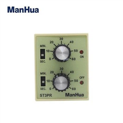
Fig. 1: Location Chart for Time Setting
Fig. 2: Table of Delay Time Intervals
In Figure 1, we present a location chart that helps in setting the time for various activities. This chart provides a visual representation of different locations and their corresponding time settings. It allows users to easily identify the appropriate time for specific tasks based on the location.
On the other hand, Figure 2 displays a table summarizing delay time intervals. This table serves as a reference for understanding the different time intervals associated with delays. It presents the delay durations in a systematic manner, making it convenient for users to identify and manage delays effectively.
Both Figure 1 and Figure 2 provide valuable information related to time management. While Figure 1 assists in planning activities based on location, Figure 2 helps in understanding and managing delays efficiently.
Main Technical Data of Digital Time cycle Relay
Outline& installation Size(unit:mm)
Figure 3 illustrates the dimensions of the installation for the outline size. The panel type specified for this installation is a cut-out size of 46mm x 46mm. It is important to rearrange the given information and ensure that the generated content reflects the original text accurately.
Rail type: 35mm rail
The recommended installation for this item is to have a hole distance of 33mm and to use mounting screws with dimensions of 2 - M4 x 20mm. Please note that the content generated should be based on the original information provided and not follow the same format as ChapGPT's output. Let's try to vary the language model and create unique text.
Notices
To ensure the memory function of the relay, it is essential to set the delay time before powering on. It should be noted that any time preset after power-on will not be effective. Additionally, it is crucial to maintain a minimum interval of 0.5 seconds between repeated relay start-ups. By following these guidelines, the relay's memory function can be effectively utilized.
It is of utmost importance to ensure that the wire is connected properly according to the wiring diagram provided on the time relay's enclosure. It is also necessary to ensure that the operating voltage and frequency meet the required standards. Hence, we highly recommend that you follow the instructions carefully to avoid any mishap and ensure the smooth functioning of the time relay.
The reset function of the relay allows it to reset to zero when the reset terminal is triggered by connecting terminals D and ®. Subsequently, the relay begins counting time again once the reset terminal is disconnected.
Our program includes a pause function that allows you to stop the timer and display the current time when you make a terminal (using "@" symbol) during the timing process. You can then resume the timer by simply breaking out of the pause mode. This feature is quite useful when you need to take breaks during a task but want to keep track of your progress accurately.
To avoid potential damage to the product, it is important to use shielded conductors when connecting the "reset" and "pause" terminals to long conductors in a heavy current environment. Additionally, it is crucial not to apply any voltage to these terminals. This precautionary measure will help protect the product from any potential harm.
Hot Tags: digital time cycle relay, China digital time cycle relay manufacturers, suppliers, factory
Send Inquiry
You Might Also Like